Der Turing-Ring ist eine einfache Turingmaschine mit einem WS2812b-LED-Ring ("Neopixel") und einem Arduino Nano, der ursprünglich 2021 von Mark Wilson erstellt und gebaut wurde. In diesem Beitrag wird das Projekt unter Verwendung der Original-Software nachgebaut. Allerdings wird hier ein spezielles Gehäuse mit dem Ender-3 Pro gedruckt.
Das folgende Schema zeigt den orignalen Aufbau des Autors:
USB
+---||||---+ Pwr
| Nano | +----+
+-----------+ | | [+5V]--+ 5V |<===
| LED Ring | | | [Gnd]--+ Gnd|<===
| | | | +----+
| 5V +--[+5V] | |
| Gnd +--[Gnd] [BTN]--+ A2 | +------------+
| DIN +--[RNG] [RNG]--+ A3 | | Rotary/PB |
+-----------+ [SDA]--+ A4 | | |
[SCL]--+ A5 | [BTN]--+ Button |
[+5V]--+ 5V D3 +---------+ ENC_B |
[Gnd]--+ Gnd D2 +---------+ ENC_A Gnd+--[Gnd]
| | +------------+
+----------+
+------------+
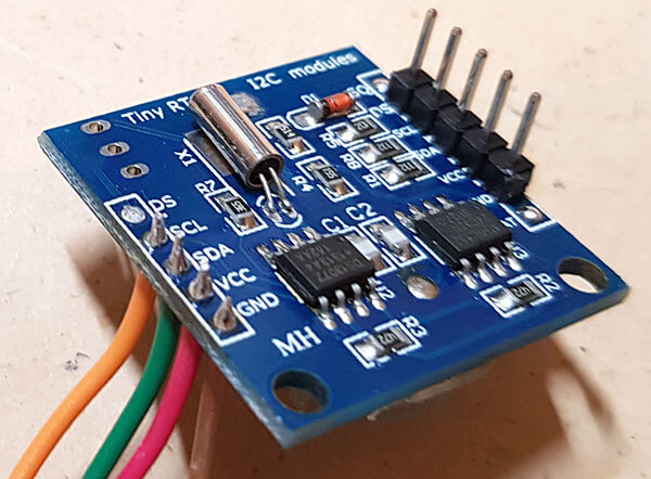
| RTC/DS3231 |
| {0x68} |
| 5V +--[+5V]
| Gnd +--[Gnd]
| SDA +--[SDA]
| SCL +--[SCL]
+------------+
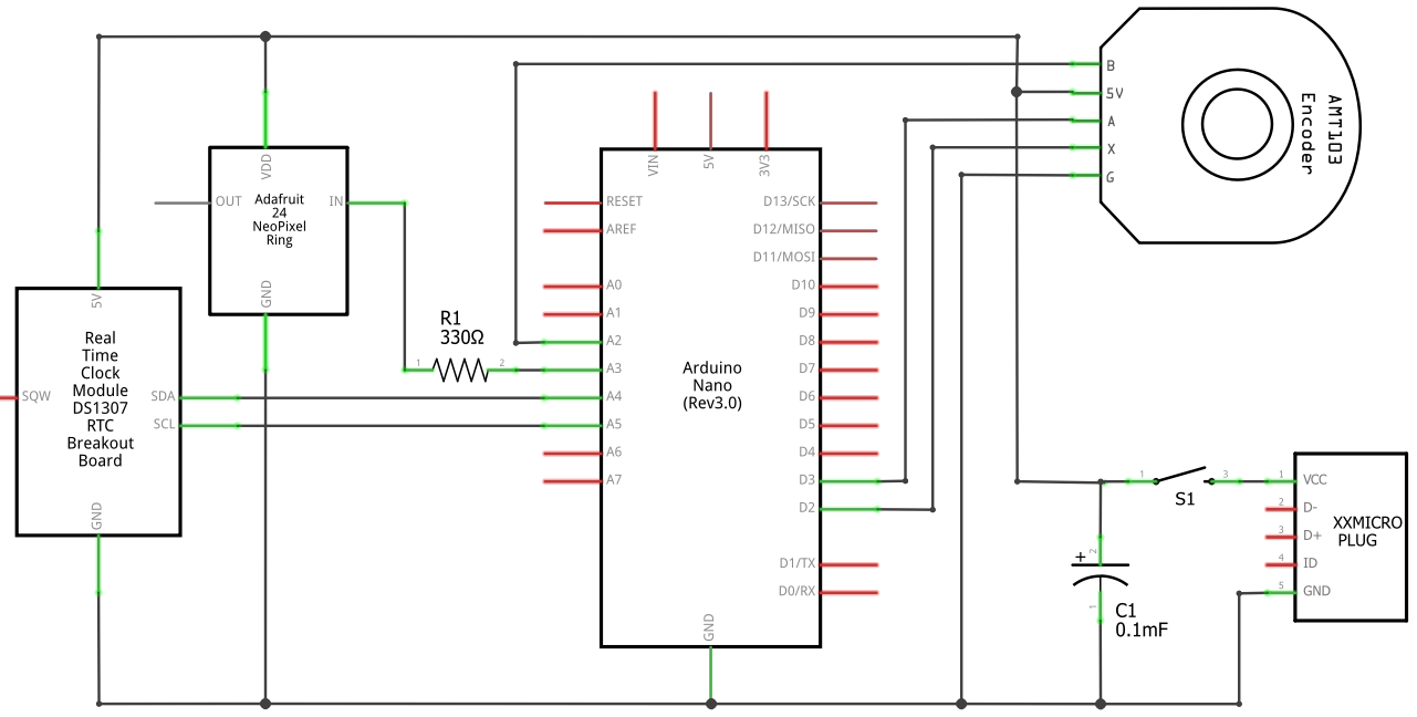
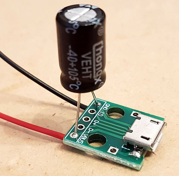
Ich habe aus sicherheitsgründen zwei kleine Modifikationen vorgenommen, die im folgenden Schaltplan zu sehen sind: ein 100µF Elektrolytkondensator (C1) zur Stabilisierung der Spannung und einen 330Ω-Widerstand (R1) zum Schutz des WS2812b-Eingangs. Zuätzlich habe ich einen Kippschalter (S1) verbaut, damit das USB-Kabel nicht immer an- und abgesteckt werden muss und somit die Buchse schont.
Den Sketch für den Turing-Ring kann unter https://github.com/funnypolynomial/Turing-ring/ heruntergeladen werden. Vor dem Kompilieren in der Arduino-IDE sind noch die folgenden beiden Libraries zu installieren: RotaryEncoder und Adafruit_NeoPixel.
Bei älteren Typen des Arduino Nano kann es notwendig sein, dass zum Hochladen des Sketches
der alte Bootloader ausgewählt werden muss:
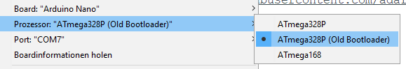
Nun sollte der Sketch fehlerfrei kompilieren und das Programm auf den Arduino Nano hochladen.
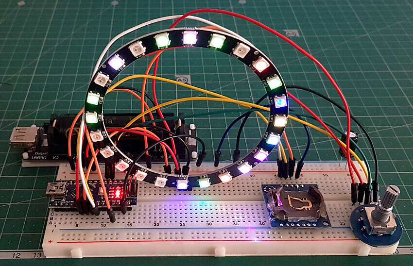
Bei Starten wird der User mit einem kleinen LED-Farbenspiel begrüßt, dann blinkt die LED
an Position A...
Im Original wurde ein Gehäuse aus Kunststoff mit einem Laser-Cutter gefertigt. Hier habe ich mich für eine eigene Kreation für den 3D-Drucker entschieden. Außerdem war der Durchmesser meines LED-Ring größer als im Original.

Das Gehäuse besteht aus der eigentlichen Box und dem Deckel (Cap). Beide sind zwar in derselben Datei, sollten aber unabhängig voneinander in eine STL-Datei umgewandelt werden.
turing_box.scadDas Gehäuse kann mit den folgenden Labels beschriftet werden:
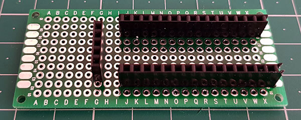
Während das Gehäuse langsam im 3D-Drucker Gestalt annimmt, kann die Elektronik vom Breadboard auf eine richtige Platine verlötet werden, um somit im Gehäuse Platz zu finden.

Der folgende Text ist der Datei readme.txt aus dem Github-Repository entnommen:
This simple Turing Machine implementation uses a *ring* of 24 RGB LEDs as the tape.
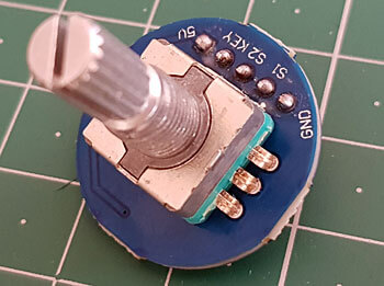
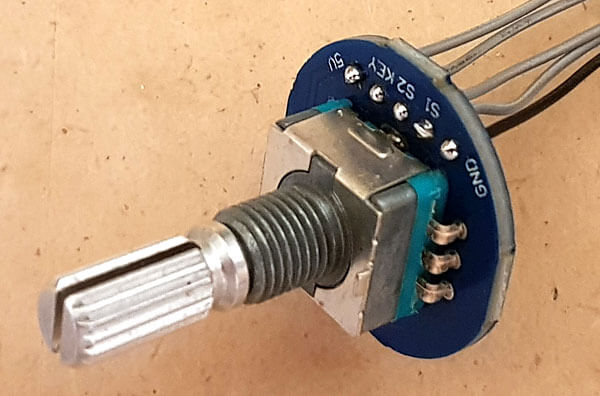
Interaction with the machine is via a rotary encoder with a built-in push-button.
The machine supports 11 States, X (Halt) and A-J, and 11 Symbols, x (Blank) and a-j.
Symbols and States are represented by LED colours, a/A=red, b/B=green etc. x/X is blank/black.
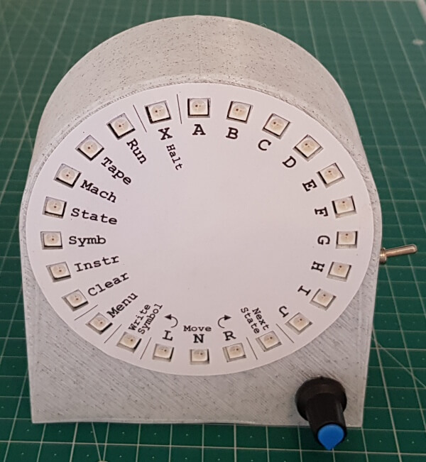
The machine starts in *Tape* mode, showing the symbols on the tape.
A cursor blinks, initially at the 12 O'Clock position. Turning the encoder knob moves the cursor around the ring.
Pressing the button enters the *Editor* mode and the ring displays items to be selected, corresponding to the labels around the ring.
Depending on the context, the letter labels represent states (A, B), symbols (a, b), or items in a list.
State/Symbol/List: Colours:
|Halt
| X | A B Black Red Green
Editor: Run C Blue
Tape D Yellow
Mach E Aqua
State F Fuchsia
Symb o G White
Instr H Orange
Clear I Malachite
Menu J Purple
Instruction:
|Write |L N R|Next |
|Symbol Move State|
The cursor starts at 12 O'Clock. Arranged clockwise from there are the available symbol colours, and one step anti-clockwise is x/Blank.
Selecting any of these (by pressing the button) will return to Tape mode with the symbol at the original cursor set to the selected value.
The cursor advances one cell clockwise.
There are other choices available in Editor mode, indicated by their corresponding LED being green. White LEDs indicate the current context.
Editor mode shows Tape+Symb as context.
Possible selections in Editor mode are:
Run: returns to Tape mode and runs the machine (see Running below)
Tape: returns to Tape mode.
Mach: edits the machine (see Editing below)
Clear: clears the tape to x/Blank and returns to Tape mode
Menu: offers auxiliary functions (see Auxiliary below)
Selecting an un-lit or white LED goes back to Tape mode.
These Editor selections are also available directly from Tape mode by *pressing and holding* the button.
A long press on Tape restores the tape to what it was at the start of the previous Run.
--- Running ---
Running starts in state A with the read/write head at the 12 O'Clock position and continues until the state is set to X/Halt
While running, turning the knob changes the speed. Pressing the button stops.
--- Editing ---
The Turing Machine consists of 10 States A-J. A is the start state. X is the Halt state.
Each state is a set of 11 Instructions defined as:
if symbol s is read under the head then
write symbol s',
move L(eft), R(ight), or N(ot at all) and
change state to S.
On entering Mach(ine) mode, the display lists all 10 editable states A-J and some other Editor items (the context is Mach+State).
Selecting Clear resets the Machine to defaults.
Selecting a State letter lists 11 possible input symbols (the context is Mach+Symb). As input symbols are highlighted, the Instruction area updates.
Selecting State goes back to selecting a state (up a level).
Selecting Clear resets the State to defaults.
Selecting an input symbol edits the Instruction (the context is Instr). The input symbol is still shown, the cursor is on Write Symbol.
Selecting the Write Symbol lists symbol to write (context is Symb+Instr). Selecting either L, N or R chooses that direction (shown in white).
Selecting Next State lists states to transition to (context is State+Instr).
Selecting Symb goes back to selecting an input symbol (up a level).
By default the entire machine is initialised to: "write x, no move, Halt" for all states and all input symbols.
This means the machine must be fully defined, if a state encounters a symbol it has no instruction for, the machine will halt.
But this can be changed, see "not-defined" in Machine::GetInstruction()
--- Auxiliary ---
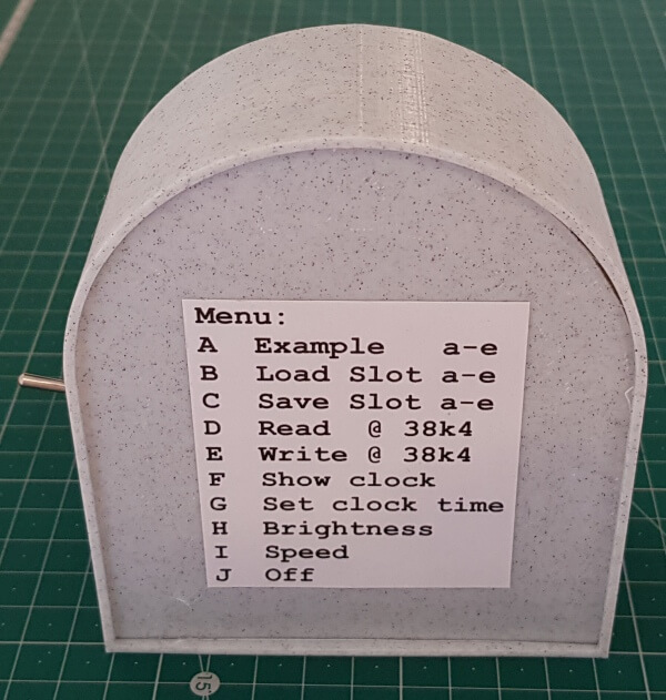
To simplify the face of the Machine, choices under this Menu are listed on the back of the enclosure.
Selecting this item changes the display to highlight a number of State letters in green.
Picking one of these performs the operation then returns to Tape mode.
The list of operations is:
A: Load an example. This offers a list of symbol letters, corresponding to a few example machine and tape combinations. See Examples below.
B: Load from slot. The display changes to a pick list of symbols a-e, picking one will load the machine and tape from the selected "slot" in EEPROM.
C: Save to slot. The display changes to a pick list of symbols a-e, picking one will save the machine and tape into the selected "slot" in EEPROM.
D: Read at 38k4. Reads a terse textual version of the machine and tape from the COM port at 38k4 baud. See Serial below.
E: Write at 38k4. Writes a terse textual version of the machine and tape to the COM port at 38k4 baud. See Serial below.
F: Clock. Because why not?
Displays the time: the hour is shown as a blue LED, the minutes as a blinking green LED. The hour positions s are marked by orange LEDs
Pressing the knob returns to Tape.
G: Set time. Sets the time for above. Turn the knob to alter the hour or minute, press the knob to set it.
H: Brightness. Turn the knob to increase or decrease the LED brightness. Press the button to set it. The LEDs can be really bright! The maximum here is ~50%.
I: Speed. Turn the knob to increase or decrease the delay between machine steps. Press the button to set it. The minimum is no additional delay, the maximum is 100ms
Selecting State will toggle the Animate setting and exit.
If Animate is on, the current state will be shown during the delay, before the tape is updated. Extra colourfulness!
J: Off. Turns the LED display off. Turning the knob or pressing the button turns it on again.
The speed, brightness, and Animate flag are stored in EEPROM.
--- Examples ---
a: Flips black to blue and vice versa
b: Cycle red/green/blue
c: Binary increment
d: Duplicate. Tape is x, followed by N White. Tape becomes x, followed by N White, x, followed by N White
e: Binary add. 1=White/g, 0=Blue/c. 00110110 00101011 -> 01100001
--- Serial ---
--- Input:
Configure the terminal to set New-line transmit to be LF (\n). The input is line oriented:
a line for each state, listing instructions
a final line listing the tape symbols
A state line is of the form:
<state>=<input symbol>:<output symbol><direction><new state>,<input symbol>:<output symbol><direction><new state>,...<input symbol>:<output symbol><direction><new state>
Where
<state> is A-J,
<input symbol> is a-j or x,
<output symbol> is a-j or x,
<direction> is L, N or R
<output state> is A-J, or X
The order of the states and the order of the instructions doesn't matter.
Additionally symbols can be specified by the first 3 letters of the colour name, starting with a capital letter:
Bla, Red, Gre, Blu, Yel, Aqu, Fuc, Whi, Ora, Mal & Pur
for X A B C D E F G H I J
Also, states X, A-I can be specified as a single digit, 0-9.
Also, </|/> or -/=/+ can be used instead of L/N/R.
Also, <space> or _ can be used instead of symbol x.
Thus "A=x:gRD,d:dNX,g:xRA\n" could also be read in as "1=Bla:WhiR4,Yel:YelN0,Whi:BlaR1"
The tape is just a line of 24 symbols, a-j or x, or alternatives as above.
Example 'a' above is these two lines:
A=x:cRA,c:xRA
xxxxxxxxxxxxcccccccccccc
--- Output:
The output format is the same as the input format above. Only those states which have some instructions defined are listed, plus the tape.
--- Hello World ---
Define a very basic Turing machine as follows.
The machine has one state A, if it reads black/x it writes white/g, and vice versa, in both cases it moves Right and remains in the same state.
Starting in Tape mode, select:
Label Description
---------------------------
A enter Editor mode
Mach edit Machine
A edit State A
X instruction when reading x (black)
Write Symbol pick Symbol to write
G write g (white)
R move Right
Next State pick next State
A remain in State A
Symb back to input Symbols
G instruction when reading g (white)
Write Symbol pick Symbol to write
X write x (black)
R move Right
Next State pick next State
A remain in State A
Run run!
Skip the first two steps by pressing-and-holding Mach from Tape mode.