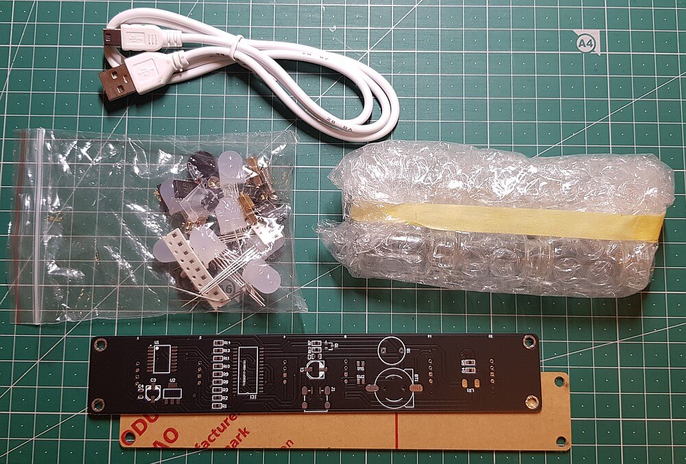
Vor Kurzem ist mir ein interessanter Bausatz auf Aliexpress ins Auge gefallen, den man unter einem
der folgenden Links beziehen kann: Creative RGB Colour Clock Kits 51 SCM oder
Creative RGB Colour Clock Kits 51 SCM oder
Creative RGB Colour Clock Kits 51 SCM oder
Creative RGB Colour Clock Kits 51 SCM oder
Creative RGB Colour Clock Kits 51 SCM.
Der Preis beläuft sich auf EUR 10.- und man erhält ein Kit, welches nach dem Zusammenbau die aktuelle Uhrzeit als Farben kodiert
mittels 10mm RGB-LEDs anzeigt.
Im Folgenden werden der Zusammenbau und die Funktionsweise der fertigen Uhr beschrieben.
Für den Zusammenbau werden einige Grundlegende Werkzeuge und Hilfsmittel benötigt.

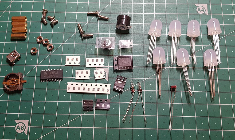
| Beschriftung | Bauteil |
|---|---|
| R1-R3, R12 | 120Ω (121) Widerstand |
| R4-R5 | 1MΩ (105) Widerstand |
| R7 | 1kΩ Widerstand |
| R8-R11, R13-R14 | 10kΩ Widerstand |
| C1 | 220µF Elektrolyt-Kondensator |
| C2 | 100nF (104) SMD-Kondensator |
| C3 | 10µF Elektrolyt-Kondensator |
| C4 | 100nF (104) SMD-Kondensator |
| L1, L2 | SMD-LED |
| L3-L8 | 10mm RGB-LED |
| LR1 | Fotowiderstand (LDR) |
| Q1 | S9012 (2T1) PNP-Transistor |
| U1 | DS3231 Echtzeituhr-IC (RTC) |
| U2 | ASM1117 Spannungsregulator 3,3V 1A |
| IC1 | 15W413AS STC Mikrocontroller |
Zunächst werden alle kleinen SMD-Bauteile, d.h. Widerstände, Kondensatoren, ICs, Spannungsregler und LEDs auf die Platine gelötet. Gerade beim Verlöten der Chips sollte nicht mit Flussmittel gespart werden, damit die Lötstellen gut gelingen. Vor allem bei den ICs, Elektrolyt-Kondensatoren und LEDs gut auf die Polarität achten!
Wer unsicher beim Löten mit SMD-Komponenten ist kann sich Tipps in den beiden Videos How to solder SMD ICs: An actually useful tip for beginners oder EEVblog #997 - How To Solder Surface Mount Components holen.
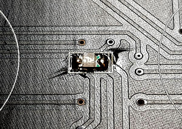
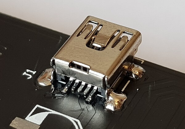
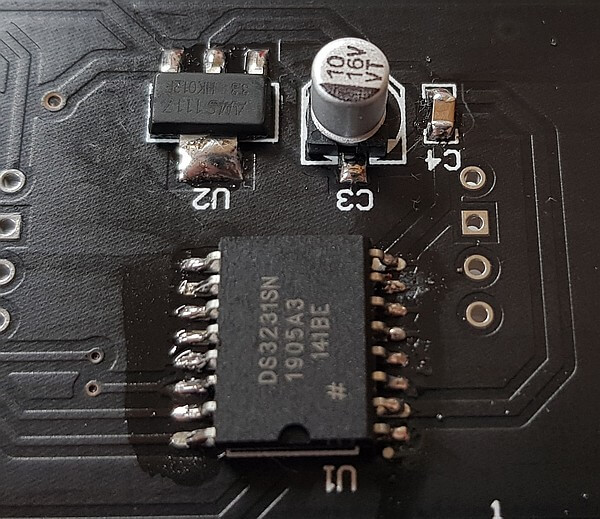
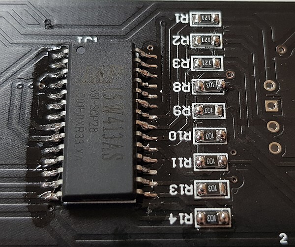
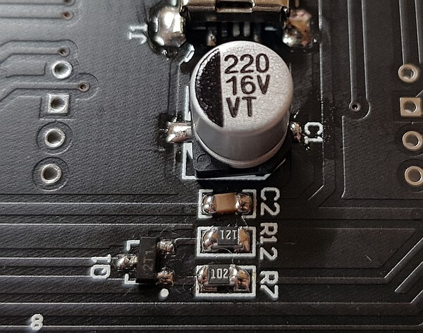
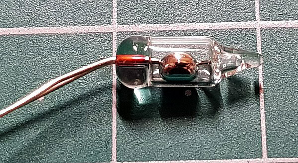
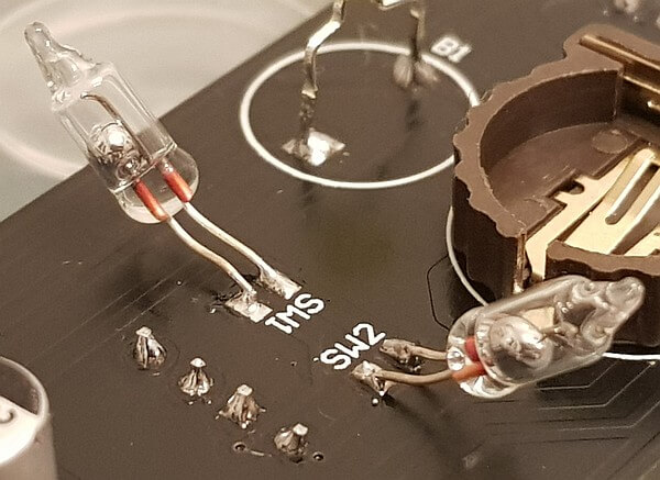
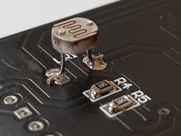
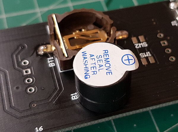
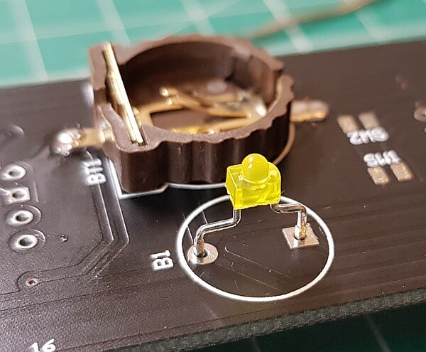
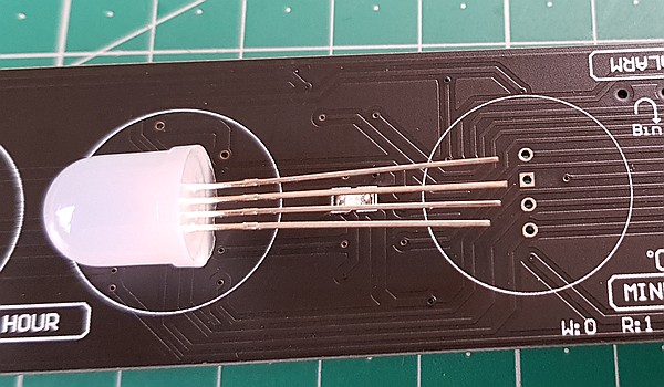

Bei mir ist nach dem Anlegen der Spannung nur die kleine 1,8mm LED bzw. der Buzzer angegangen und ansonsten blieben alle weiteren LEDs dunkel. Auch nach Durchmessung und genauerer Überprüfung konnte ich die Uhr nicht in Gang setzen. Evtl. ist der MCU oder RTC defekt oder eine Lötstelle kalt. Dies bedarf noch weiterer Prüfung...
...Nach langem Prüfen und Überlegen, wo das Problem liegen könnte hatte ich zunächst den PNP-Transistor in Verdacht,
dass der durch das Einlöten verbraten wurde, aber auch nach dem Austausch durch einen neuen S9012 (es lagen im Bausatz
zum Glück einige Ersatzteile bei) war das Resultat dasselbe.
Letztendlich hat sich herausgestellt, dass ein Pin des Mikrocontrollers keinen Kontakt zur Platine hatte und das Problem
war nach mühevollem SMD-Gebastel endlich erledigt.
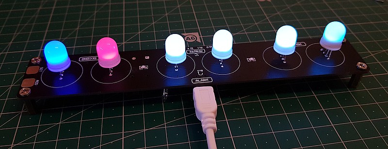
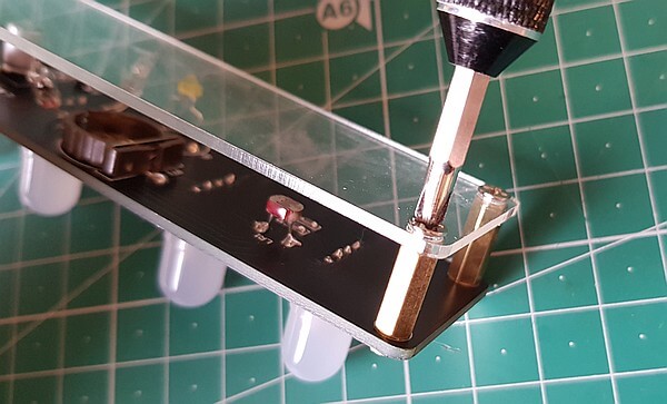
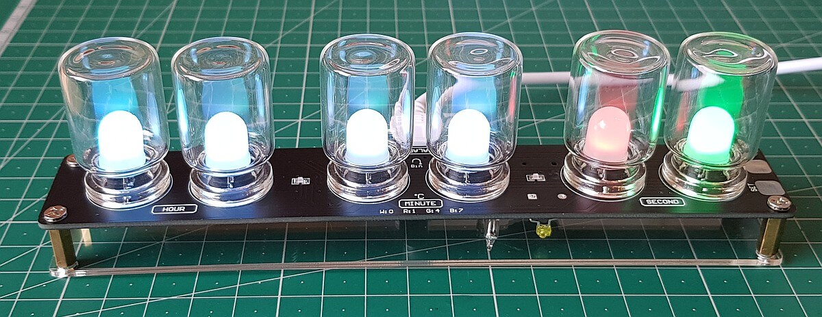
Damit die eingestellte Uhrzeit erhalten bleibt, sollte man in den dafür vorgesehenen Batteriehalter noch eine CR1220 Lithium-Knopfzelle einlegen.
Die Uhr zeigt getrennt Stunde, Minuten und Sekunden im 24h-System an, wobei hier jeweils die beiden Ziffern als ein Farbwert durch eine RGB-LED dargestellt wird. Ähnlich den Farbbändern bei Widerständen. Die folgende Farbtabelle gibt Aufschluss über die aufleuchtenden Ziffern:
| Farbe | Ziffer |
|---|---|
| weiß | 0 |
| rot | 1 |
| orange | 2 |
| gelb (grünlich) | 3 |
| grün | 4 |
| cyan (grünlich) | 5 |
| cyan (bläulich) | 6 |
| dunkelblau | 7 |
| violett | 8 |
| pink/magenta | 9 |
Der DS3231-Chip ist eine Echtzeituhr mit Notfall-Stromversorgung über eine Knopfbatterie, d.h. die eingestellte Uhrzeit bleibt erhalten, wenn die Spannungsquelle nicht mehr angeschlossen ist. Es gibt einen Alarm und (halb?-)stündliche Töne (vorausgesetzt, man ersetzt den Buzzer nicht durch eine LED)
Zum Stellen der Zeit kippt man die Uhr 90° nach vorne (Beschriftung beachten) und es wird durch Blinken aller LEDs angezeigt, dass man sich im Edit-Modus befindet. Durch Tippen des "Set"-Touchpads auf der rechten Seite stellt man die aktuell blinkende Ziffer. Durch einmaliges Tippen auf das "Add"-Touchpad springt man eine Ziffer weiter. Wenn man am Ende der 6 Ziffern angekommen ist, drückt man erneut "Set" und die Zeit ist gespeichert.
Um einen Alarm zu aktivieren, muss man die Uhr um 90° nach hinten kippen und dann auf "Add" tippen. Die linke,
blaue SMD-LED leuchtet dann auf (oder erlischt, wenn man den Alarm wieder entfernt).
Die Alarmzeit stellt man ähnlich wie die Uhrzeit, nur dann man eben die Uhr um 90° nach hinten und nicht nach vorne kippt.
Wenn der Alarm ertönt, dann schaltet man ihn durch Tippen auf "Add" oder "Set" wieder aus.
Tilt the clock forward as shown to set the time using the touch buttons. The “Set” button moves between digits, and the “Add” button
adds one to the count with each press. You need to scroll through all six LEDs with the set button. Once the clock is set to the correct
time, just press the set button one more time and the time will be set.
When setting the alarm, the two SMD LEDs will light up to show the alarm is on. You can’t set the alarm time unless the LEDs are lit.
To turn the alarm off, tilt the clock back (the opposite direction to when setting the time) and just press the “Add” button without first
pressing the set button. The two LEDs should go out to tell you the alarm is off.
Setting the alarm is a little quirky. Rotate the clock 180 degrees so that the USB connector is pointing towards you and then tilt the clock
towards you. You are effectively tilting it back, but it makes it easier to set this way, and the clock is designed to transpose the LED
positions during alarm setting, so that the seconds LEDs actually display the alarm hours setting and the minutes LEDs display the alarm
minutes setting (but transposed). This seems odd, but works well in practice.
You set the alarm in the same way as the time—the set key switches between setting the hours and minutes while the add key increments
by one. Note that you don’t set the tens and units individually when setting the alarm time, you just scroll through 0-23 for the hours and
0-59 for the minutes. Once the alarm time is set, just press set again to finalise the alarm setting procedure. The two SMD LEDs should
be lit to indicate that the alarm is on.
When the alarm sounds, just touch either touch switch to turn it off.
The clock also flashes the LEDs and beeps every half hour by default. If the beeping annoys you it can be turned off by tilting the clock
forward as if you are going to set it. When the clock is in beeping mode, the left-hand SMD LED will light when you tilt the clock for-
ward. Just press the “Add” button (without first pressing the set button) and the LED will go out and the clock will stop beeping. Note
that this setting isn’t saved, and so if you power the clock down, it will start beeping on the half-hour again when you power it back up.
For a permanent solution just don’t install the piezo sounder, although this will disable the alarm of course.
The clock will also display temperature—with it sitting upright just touch the “Set” or “Add” buttons and only the two middle RGB
LEDs will light. We have found this to be not overly accurate, however.