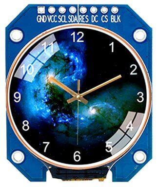
Eine weit verbreitete Art der TFTs sind mittlerweile die runden Module auf der Basis des GC9A01-Chips. Sie bieten eine Auflösung von 240×240 Pixeln und haben 64k-Farbtiefe. Einsatzgebiete sind beispielsweise Smartwatches oder technische Anzeigen, wie Tachometer.
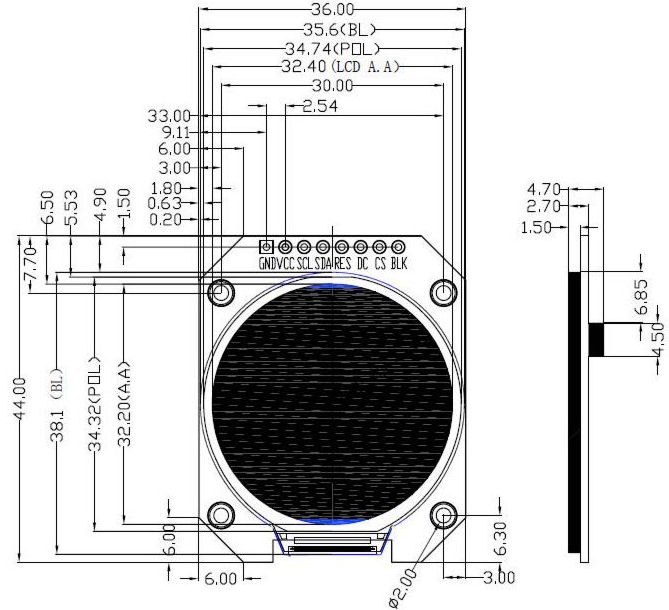
| Größe | 1,28 Zoll |
|---|---|
| Auflösung | 240×240 (RGB) |
| Treiberchip | GC9A01 |
| Schnittstelle | SPI (4-Wire) |
| Pixelgröße | 0.135mm × 0,135mm |
| Betriebsspannung | 3,3V |
| Stromaufnahme | 20mA |
| Temperaturbereich | -20°C bis ~70°C |
Wichtig: Das hier verwendete GC9A01-Modul wird mit 3,3V betrieben und besitzt keinen Spannungsregler, so dass ein Betrieb mit 5V das Modul zerstören kann!
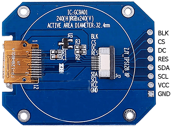
| GC9A01 | Funktion | ESP32 |
|---|---|---|
| BLK | Backlight Control (LED-Hintergrundbeleuchtung) | GPIO22 (D22) |
| CS | Chip Select (CS SPI) | GPIO5 (D5) |
| DC | Data/Command Select | GPIO27 (D27) |
| RES | Reset (auch: RST) | GPIO33 (D33) |
| SDA | Data Input (SDI/Mosi SPI) | GPIO15 (D15) |
| SCL | Clock Input (SCK/SCLK SPI) | GPIO14 (D14) |
| VCC | Spannungsversorgung (3,3V) | 3V3 |
| GND | Ground/0V | GND |
(siehe auch: Anschlüsse des ESP32
Im Folgenden habe ich die Library
https://github.com/Bodmer/TFT_eSPI
verwendet, die vor der Verwendung für das verwendete TFT-Modul konfiguriert werden muss. Dazu
muss man die Datei User_Setup.h editieren (liegt unter Windows10 im Ordner
"C:\Users\MyUser\Documents\Arduino\libraries\TFT_eSPI-master"). Der Inhalt muss
folgender sein:
#define USER_SETUP_INFO "User_Setup"

#define GC9A01_DRIVER
#define TFT_SDA_READ

#define TFT_WIDTH  240
#define TFT_HEIGHT 240

// The hardware SPI can be mapped to any pins
#define TFT_MOSI 15  // might be written as "SDA"
#define TFT_SCLK 14
#define TFT_CS    5  // Chip select
#define TFT_DC   27  // Data Command
#define TFT_RST  33  // Reset pin
#define TFT_BL   22  // LED back-light (BLK)

#define LOAD_GLCD   // Font 1. Original Adafruit 8 pixel font needs ~1820 bytes in FLASH
#define LOAD_FONT2  // Font 2. Small 16 pixel high font, needs ~3534 bytes in FLASH, 96 characters
#define LOAD_FONT4  // Font 4. Medium 26 pixel high font, needs ~5848 bytes in FLASH, 96 characters
#define LOAD_FONT6  // Font 6. Large 48 pixel font, needs ~2666 bytes in FLASH, only characters 1234567890:-.apm
#define LOAD_FONT7  // Font 7. 7 segment 48 pixel font, needs ~2438 bytes in FLASH, only characters 1234567890:-.
#define LOAD_FONT8  // Font 8. Large 75 pixel font needs ~3256 bytes in FLASH, only characters 1234567890:-.

#define SPI_FREQUENCY       27000000
#define SPI_READ_FREQUENCY  20000000
Hinweis: Die Pins auf dem ESP32 können auch eine andere Belegung haben.
#include <SPI.h>
#include <TFT_eSPI.h>

TFT_eSPI tft = TFT_eSPI();

void setup()
{
   tft.init();
   tft.fillScreen(TFT_BLACK);

   // Set "cursor" to (50,50) and select font 4
   tft.setCursor(50, 50, 4);

   // Set the font colour to be white with a black background
   tft.setTextColor(TFT_WHITE, TFT_BLACK);

   // We can now plot text on screen using the "print" class
   tft.println("Hello, World!");
}

void loop() {}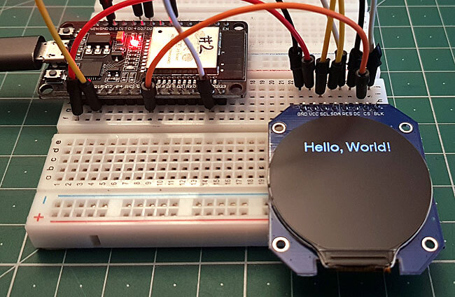
#include <SPI.h>
#include <TFT_eSPI.h>
TFT_eSPI tft = TFT_eSPI();
int clkHours = 3, clkMinutes = 48, clkSeconds = 18;
const int mx = TFT_WIDTH / 2;
const int my = TFT_HEIGHT / 2;
const int r = TFT_WIDTH / 2;
void setup()
{
tft.init();
tft.setRotation(0);
tft.fillScreen(TFT_BLACK);
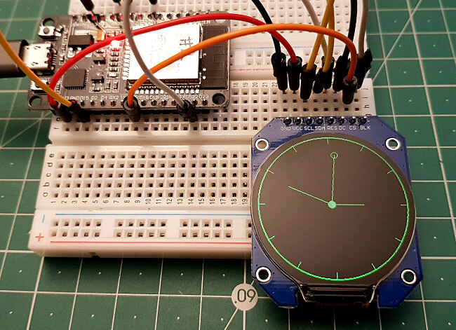
tft.drawCircle(mx, my, r - 1, TFT_GREEN);
tft.drawCircle(mx, my, r - 2, TFT_GREEN);
for (int i = 0; i < 360; i += 30) {
float sx = cos((i - 90) * DEG_TO_RAD) * (r - 1);
float sy = sin((i - 90) * DEG_TO_RAD) * (r - 1);
tft.drawLine(mx, my, mx + sx, my + sy, TFT_GREEN);
}
tft.fillCircle(mx, my, r - 13, TFT_BLACK);
}
void loop()
{
progressTime();
showTime();
delay(1000);
}
void progressTime()
{
clkSeconds++;
if (clkSeconds >= 60) {
clkSeconds = 0;
clkMinutes++;
if (clkMinutes >= 60) {
clkMinutes = 0;
clkHours++;
if (clkHours >= 12) {
clkHours = 0;
}
}
}
}
void showTime()
{
static int zxSec, zySec, zxMin, zyMin, zxHrs, zyHrs;
tft.drawLine(mx, my, mx + zxSec, my + zySec, TFT_BLACK);
tft.drawLine(mx, my, mx + zxMin, my + zyMin, TFT_BLACK);
tft.drawLine(mx, my, mx + zxHrs, my + zyHrs, TFT_BLACK);
tft.drawCircle(mx + zxSec, my + zySec, 5, TFT_BLACK);
float rad = ((float)clkSeconds / 60) * 360 - 90;
zxSec = (int)(cos(rad * DEG_TO_RAD) * 87);
zySec = (int)(sin(rad * DEG_TO_RAD) * 87);
rad = ((float)clkMinutes / 60) * 360 - 90;
zxMin = (int)(cos(rad * DEG_TO_RAD) * 75);
zyMin = (int)(sin(rad * DEG_TO_RAD) * 75);
rad = ((float)(clkHours * 60) / 720) * 360 - 90;
zxHrs = (int)(cos(rad * DEG_TO_RAD) * 50);
zyHrs = (int)(sin(rad * DEG_TO_RAD) * 50);
tft.drawLine(mx, my, mx + zxSec, my + zySec, TFT_GREEN);
tft.drawLine(mx, my, mx + zxMin, my + zyMin, TFT_GREEN);
tft.drawLine(mx, my, mx + zxHrs, my + zyHrs, TFT_GREEN);
tft.drawCircle(mx + zxSec, my + zySec, 5, TFT_GREEN);
tft.fillCircle(mx, my, 6, TFT_GREEN);
}
#include <SPI.h>
#include <TFT_eSPI.h>
TFT_eSPI tft = TFT_eSPI();
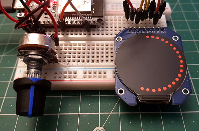
// Potentiometer is connected to GPIO 34 (Analog ADC1_CH6)
#define PIN_POTENTIOMETER 34
const int mx = TFT_WIDTH / 2;
const int my = TFT_HEIGHT / 2;
const int r = TFT_WIDTH / 2;
void setup()
{
tft.init();
tft.setRotation(0);
tft.fillScreen(TFT_BLACK);
}
void loop()
{
static int potValue = 0, potAngle = 0, potAngleOld = 0;
potValue = analogRead(PIN_POTENTIOMETER);
potAngle = map(potValue, 0, 4095, 0, 360);
if (potAngle / 10 != potAngleOld / 10) {
for (int i = 0; i < potAngleOld; i += 10) {
float sx = cos((i - 90) * DEG_TO_RAD) * (r - 8);
float sy = sin((i - 90) * DEG_TO_RAD) * (r - 8);
tft.fillCircle(mx + sx, my + sy, 5, TFT_BLACK);
}
for (int i = 0; i < potAngle; i += 10) {
float sx = cos((i - 90) * DEG_TO_RAD) * (r - 8);
float sy = sin((i - 90) * DEG_TO_RAD) * (r - 8);
tft.fillCircle(mx + sx, my + sy, 5, TFT_RED);
}
potAngleOld = potAngle;
}
delay(100);
}